پیوند ها

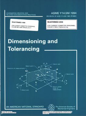
اندازه و تلرانسگذاری هندسی
CONTENTS
1 Scope, Definitions, and General Dimensioning
1.1 General
1.2 References
1.3 Definitions
1.4 Fundamental Rules
1.5 Units of Measurement
1.6 Types of Dimensioning
1.7 Application of Dimensions
1.8 Dimensioning Features
1.9 Location ofFeatures
2 General Tolerancing and Related Principles
2.1 General
2.2 Direct Tolerancing Methods
2.3 Tolerance Expression.
2.4 Interpretation ofLimits
2.5 Single Limits
2.6 Tolerance Accumulation
2.7 Limits of Size.
2.8 Applicability of RFS, MMC, and LMC
2.9 Screw Threads.
2.10 Gears and Splines
2.11 VirtuaVResultant Condition
2.12 Angular Surfaces.
2.13 Conical Tapers.
2.14 Flat Tapers
2.15 Radius
2.16 Statistical Tolerancing
3 Symbology
3.1 General
3.2 Use of Notes to Supplement Symbols
3.3 Symbol Construction.
3.4 Geometric Tolerance Symbols
3.5 Feature Control Frame Placement
3.6 Definition of the Tolerance Zone.
3.7 Tabulated Tolerances.
4 Datum Referencing
4.1 General.
4.2 Immobilization of Part
4.3 DatumFeatures
4.4 Specifying Datum Features in an Order of Precedence.
4.5 Establishing Datums
4.6 DatumTargets
5 Tolerances of Location
5.1 General.
5.2 Positional Tolerancing
5.3 Fundamental Explanation of Positional Tolerancing
5.4 Feature Pattern Location.
5.5 Projected Tolerance Zone.
5.6 Nonparallel Holes.
5.7 Counterbored Holes
5.8 Closer Control at One End of a Feature
5.9 Bidirectional Positional Tolerancing of Features.
5.10 Noncircular Features
5.11 Coaxiality Controls
5.12 Concentricity
5.13 Positional Tolerancing for Symmetrical Relationships.
5.14 Symmetry Tolerancing to Control the Median Points of Opposed or
Correspondingly-Located Elements of Features.
5.15 Spherical Features.
6 Tolerances of Form, Profile, Orientation, and Runout
6.1 General
6.2 Form and orientation Control.
6.3 Specifying Form and Orientation Tolerances
6.4 FormTolerances
6.5 Profile Control
6.6 Orientation Tolerances
6.7 Runout
6.8 Free State Variation.
Appendices
A Principal Changes and Improvements
Al General
A2 Figures
A3 Section 1, Scope, Definitions, and General Dimensioning
A4 Section 2, General Tolerancing and Related Principles
A5 Section 3, Symbology
A6 Section 4, Datum Referencing
A7 Section 5, Tolerances of Location
A8 Section 6, Tolerances of Form, Profile, Orientation, and Runout
A9 Appendix A, Principal Changes and Improvements
A10 Appendix B, Formulas for Positional Tolerancing
Al 1 Appendix C, Form, Proportion, and Comparison of Symbols.
Al2 Appendix D, Former Practices
Al3 Appendix E, Decision Diagrams for Geometric Control
Formulas for Positional Tolerancing
Bl General
B2 Formula Symbols
B3 Floating Fastener Case
B4 Fixed Fastener Case When Projected Tolerance Zone Is Used
B5 provision for Out-of-SquarenessW hen Projected Tolerance Zone is
Not Used
B6 Coaxial Features
B7 Limits andFits
Form, Proportion, and Comparison of Symbols
Cl General
c2 Form andProportion
c3 Comparison
Former Practices
Dl General
D2 Definition for Feature of Size
D3 Applicability of RFS, MMC, and LMC
D4 Tangent Radii
D5 Datum Feature Symbol
D6 ProjectedToleranceZone
Decision Diagrams for Geometric Control
El Purpose
E2 Functional Requirements
E3 Reference to Standard
E4 GeometricControls
E5 Choosing Other Controls
E6 Use of Modifiers
E7 Datums
مبلغ قابل پرداخت 52,900 تومان
برچسب های مهم